Measuring defects inside an aircraft engine is rarely as simple as spotting something on a screen. In tight engine spaces, the real challenge is getting a view that is stable, properly angled, and repeatable enough to support accurate measurement. When access is limited and the surface you need to evaluate sits around a bend or behind structural geometry, even experienced technicians can run into the same issue: a defect is visible, but the inspection setup makes it hard to quantify with confidence.
That is why measurement-focused videoscopes have become more important in modern maintenance workflows. The USA3000J-6, offered by USA Borescopes, is designed for situations where the inspection path is narrow, the target area is tucked into compact geometry, and decisions need documentation that goes beyond a photo. With a 6mm probe, joystick articulation, and dual view 3D measuring capability, it is built to help technicians capture reliable data where traditional approaches can struggle.
Why Tight Spaces Are Where Measurement Errors Happen
In open-access inspection areas, technicians can usually position the probe to get a straight-on view and maintain consistent distance. Tight spaces remove those advantages. You might be forced to inspect at an angle, through a narrow passage, or around features that limit tip control. The result is a higher chance of perspective distortion and unstable framing.
Here are the most common reasons measurement quality suffers in compact areas:
- Angle limitations
If the view is too oblique, defect edges blur into surface reflections and the shape can appear stretched or compressed. - Unsteady tip position
Tight spaces often require micro-movements to hold position. Even small drift can affect how a defect boundary is captured. - Curved and reflective surfaces
Engine components are rarely flat. Curvature changes how edges appear, and reflective alloys can hide transitions under glare. - Reduced ability to re-capture the same view
If the path is difficult, returning to the exact spot for confirmation can take time. That makes first-pass capture quality even more important.
Accurate 3D measurement is not only a matter of tool capability. It is also about controlling the variables that tight engine spaces make harder to manage. The right probe diameter and articulation control can have a direct impact on how consistently a technician can collect measurement-ready views.
The Value of a 6mm Probe in Real Engine Geometry
Probe diameter matters because it affects what inspection routes are practical. In many engine areas, a larger diameter can limit where the probe can go or force awkward positioning. A 6mm probe tends to strike a useful balance for many aircraft maintenance applications by offering access through narrower openings while still supporting robust imaging and measurement capability.
In tight spaces, a smaller diameter can help in several ways:
- More inspection paths remain usable
Narrow corridors and constrained entry points are less restrictive when the probe can pass without contact. - Less risk of forcing the insertion
A probe that fits comfortably reduces the temptation to apply extra pressure that can lead to sudden movement or unintentional contact with sensitive surfaces. - Better positioning near the target
When clearance is limited, smaller diameter can allow more deliberate approach angles, which helps with both viewing and measurement.
The real advantage is not just access. It is the ability to get into a position that supports stable imaging, then hold that position long enough to capture what you need. When the inspection is about quantifying a defect, not simply observing it, control and stability are as important as resolution.
Articulated Tip Control for Precision Positioning
Even with the right diameter, tight engine spaces can still be unforgiving. This is where articulation becomes the deciding factor. If a technician cannot steer smoothly and hold an angle precisely, it is difficult to frame a defect cleanly and capture it in a way that supports accurate measurement.
Joystick articulation is designed to improve that control by allowing deliberate movement instead of constant repositioning. In compact areas, that can reduce time spent re-acquiring the same feature and increase the chance of getting a measurement-ready view on the first pass.
Holding an angle while capturing measurement views
Measurement typically requires a stable view where the defect boundaries are clearly visible. In a tight passage, the probe tip may want to drift as the technician adjusts grip or cable tension changes. Smooth articulation control helps counteract that drift and makes it easier to hold the viewing angle steady during capture.
When a defect sits on a curved surface, even a slight change in angle can make the edge look different. The ability to maintain an exact orientation gives the measurement process a more reliable foundation.
Micro-adjustments near critical surfaces
In compact engine areas, the best view is often close to the surface, but close is also where risk increases. A sudden movement can lead to contact, and contact can blur the image or create a safety concern in sensitive areas.
Articulation control helps technicians make small, controlled adjustments rather than large corrections. That can improve image clarity, reduce blur, and help produce clean defect boundaries that measurement tools can interpret more reliably.
Step-by-Step: A Practical 3D Measurement Approach in Compact Areas
Getting accurate measurements in tight spaces is part tool capability and part disciplined workflow. The goal is to remove as much variability as possible and ensure the captures are consistent enough to support review and comparison over time.
- Start with a route plan
Know the access point, expected bends, and the likely orientation of the target surface. Planning reduces the amount of trial-and-error movement once inside. - Acquire a clean context image first
Before focusing on measurement, capture a wider view that shows location and surrounding geometry. This supports documentation and helps reviewers understand exactly where the defect sits. - Stabilize, then refine
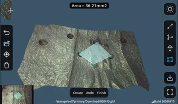
Stabilize the probe tip before zooming in mentally. In tight spaces, the instinct is often to chase the defect. Instead, hold position and use controlled articulation to bring the defect into a stable frame. - Use dual view to confirm defect boundaries
Compact geometry can hide the true edge of a defect from one angle. Dual view helps confirm whether the indication is continuous, where it starts and ends, and whether shadows are misleading the impression. - Capture the measurement-ready view
The best captures usually show the defect centered, edges well defined, and minimal glare. If the edge is unclear, reposition and re-capture rather than forcing a measurement. - Confirm with a second capture
In tight spaces, a second capture is a quality check. It helps confirm that the measurement is not a one-angle artifact.
The USA3000J-6 is built to support this kind of workflow through its diameter, articulation control, and dual view 3D measurement capabilities. For a detailed look at the configuration and inspection-oriented features, the product page for the USA3000J-6 joystick articulation 6mm dual view 3D measuring videoscope is a helpful reference.
Common Tight-Space Use Cases and How to Handle Them
Tight-space measurement needs tend to show up in similar ways across engine inspections. A few common scenarios include:
- Small nicks and dents on edges
These are easy to overestimate visually. Dual view and measurement help determine whether the feature is superficial or a concern. - Suspected crack-like indications
In compact geometry, deposits and shadows can mimic cracking. Confirming continuity across angles improves confidence before escalating the finding. - Pitting or surface distress on curved areas
Curvature makes it hard to judge depth. Measurements help quantify severity and track change over time. - Blend and repair evaluation
When assessing repaired areas, measurement-backed documentation helps confirm that the surface condition remains stable over inspection intervals.
In each scenario, the theme is the same: tight spaces increase uncertainty, so your workflow should be built to reduce it. When capture quality is marginal, re-positioning is usually faster than trying to justify a measurement based on an unclear boundary.
Accurate 3D measurements in tight engine spaces require more than a clear image. They require access, stable positioning, and the ability to validate defect geometry from more than one angle. A 6mm probe supports navigation through narrow routes, and precise articulation control helps technicians hold angles and frame defect boundaries cleanly. Dual view and 3D measurement capability add the final layer by turning what is visible into quantifiable, review-ready evidence.
For maintenance teams evaluating inspection tools, USA Borescopes offers a range of solutions across its catalog and can help match configurations to real inspection demands. To learn more about USA Borescopes or to discuss a specific engine inspection use case, readers can contact their team.
About The Author
The author is an independent aviation inspection technology specialist with deep experience in borescope workflows, defect documentation, and measurement best practices. They advise maintenance teams on selecting equipment that supports repeatable, defensible results in confined engine geometries. They are not affiliated with any manufacturer or distributor and write from a practical, field-focused perspective.